


About OSENSA's Optical Fluorescent Sensor Technology
Nearly all materials will fluoresce under the right conditions. Fluorescence can be very simply defined as the emission of light when a material is exposed to electromagnetic radiation. This emission may continue for a period of time after the initial excitation. The length of time that a material will emit is a product of a number of interactions that occur at the atomic level and the amount of energy that is absorbed. Both excitation and emission intensities behave exponentially with respect to time. This dual time-dependent behavior is a unique property that can be used to indicate what state the molecules of the fluorescent material are in.
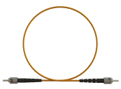
Scientists have found various classes of fluorescent materials that can be doped with specific elements to make their behaviors highly dependent on certain physical properties that are of practical interest for sensing applications. OSENSA Innovations discovered that it is possible, for instance, to use the fluorescent properties of certain crystal matrices to measure temperature, pressure, humidity, oxygen, and carbon dioxide. All of these physical properties can be measured by accurately determining the exponential time constant of the unique fluorescent material. OSENSA developed a series of highly cost-effective fiber optic temperature sensors that exploit these principles. One significant advantage that OSENSA has over competing sensing technologies is that fiber optic sensors are inherently immune to electromagnetic noise and interference. There are no metal conductors that act as antennae to transmit current and voltage. This makes OSENSA's sensors ideally suited for applications in high-voltage power transmission, microwave, and plasma environments. In addition, OSENSA's technology permits the use of inexpensive, large-core polymer plastic optical fiber in applications below 150°C. Plastic optical fiber is extremely robust and durable, and is already widely used in the automotive, industrial and telecommunication industries.
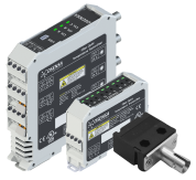
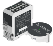
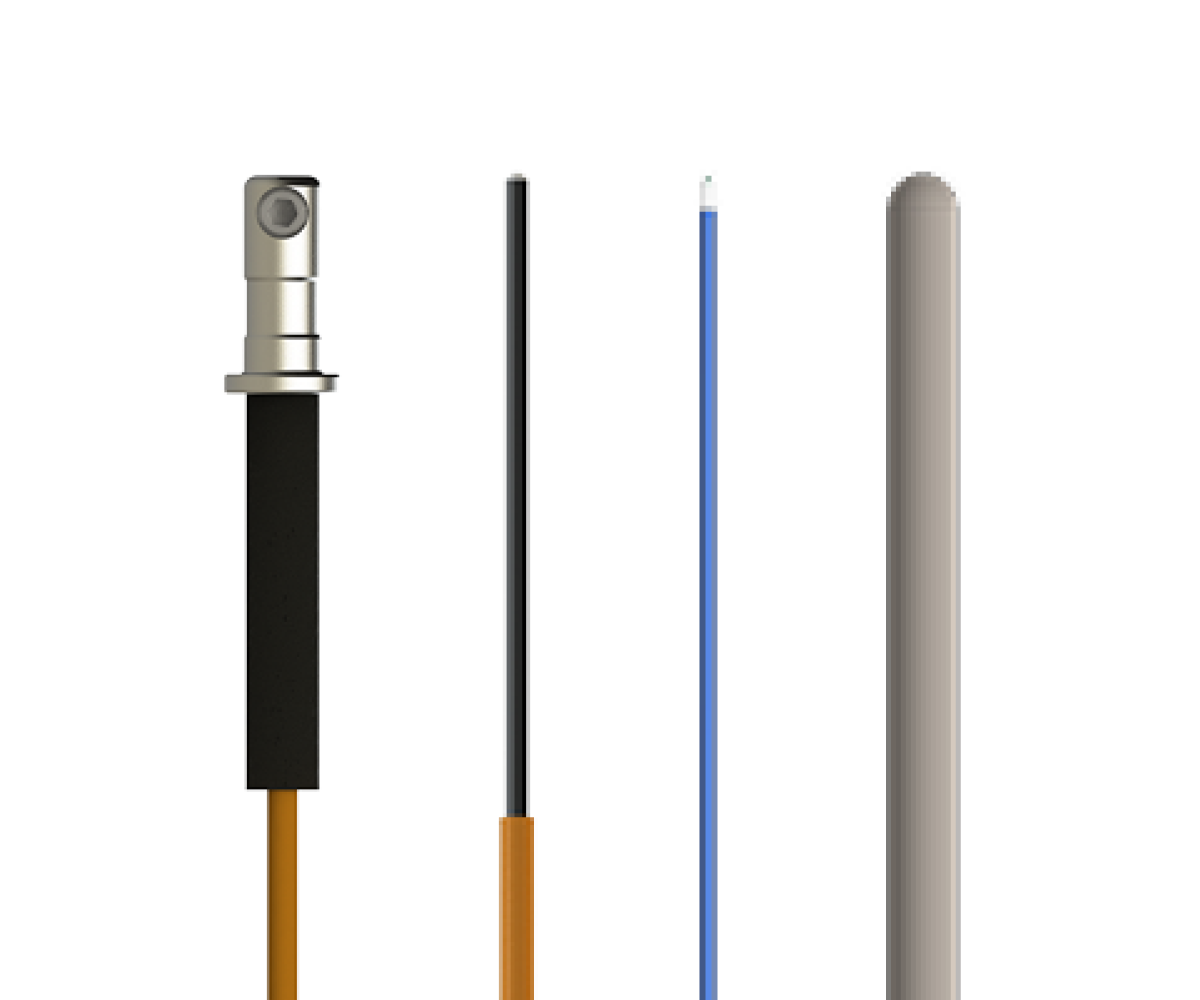
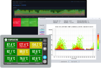
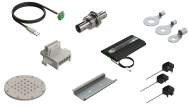
Fiber optic temperature sensors are solutions consisting of one or more fiber optic probes attached to a temperature transmitter (also known as signal conditioner) electronic device. OSENSA developed multi-channel fiber optic temperature sensors that are targeted for applications such as electrical power transmission and distribution. Unlike previous generation fiber optic signal conditioners which were bulky and expensive lab devices, OSENSA's fiber optic temperature transmitters are in similar form factor and are mounted like a thermocouple or RTD (Resistance Temperature Detector) transmitter. They are DIN rail mountable and include standard 4-20mA analog outputs as well as an industrial RS-485 serial bus for modbus communication to daisy-chained devices. OSENSA's fiber optic probes also share a similar look and feel as standard thermocouples and RTD's. Best of all, the cost of OSENSA's fiber optic temperature sensors is close to commercial RTD and transmitter combinations.

OSENSA's temperature sensing technology is also unique in that it can be both contact and non-contact. After applying a specially prepared formulation of sensitive material to an object of interest, its temperature can be read. This is a particularly valuable feature for characterizing temperatures of critical electronic components and profiling the thermal heat distribution over larger objects. A fiber optic probe can be brought close enough to the sensing material to read its temperature, without causing stem conduction losses from electrical wires, and without the need to strategically place and route thermocouple leads everywhere. The optical temperature reading is more accurate than an Infrared (IR) camera reading, and at a fraction of the cost.
Other advantages of OSENSA's fiber optic temperature sensing technology are:
- Immunity to high-voltage, high RF (radio frequency) microwave, and electromagnetic fields
- Robust polymer plastic optical fiber for simple installation and ease of handling
- Standard industrial temperature transmitter with digital and analog outputs
- Calibrated temperature accuracy of ±0.1°C
- Fast response time, contact or non-contact sensing
- Industry-leading system cost
- Temperature support from -200°C to +700°C
- Replaces thermocouples and RTD's in a variety of applications